All-in-One: Power supply + Battery charger + Back-up functions, all packaged in one box
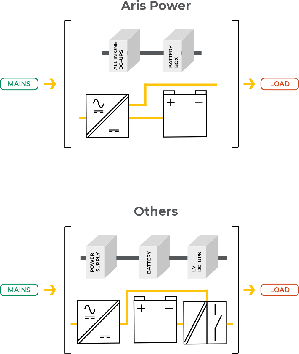
Aris Power DCU series of DC-UPS feature an All-In-One architecture, including Power supply + Battery charger + Back-up functions, all packaged in one casing.
The DCU directly takes mains input voltage and manages load and battery requirements. Other market devices instead have low voltage input and must be energized by an external power supply unit.DCU devices are therefore more functional than most others and allow more compact, cost-effective backup solutions.
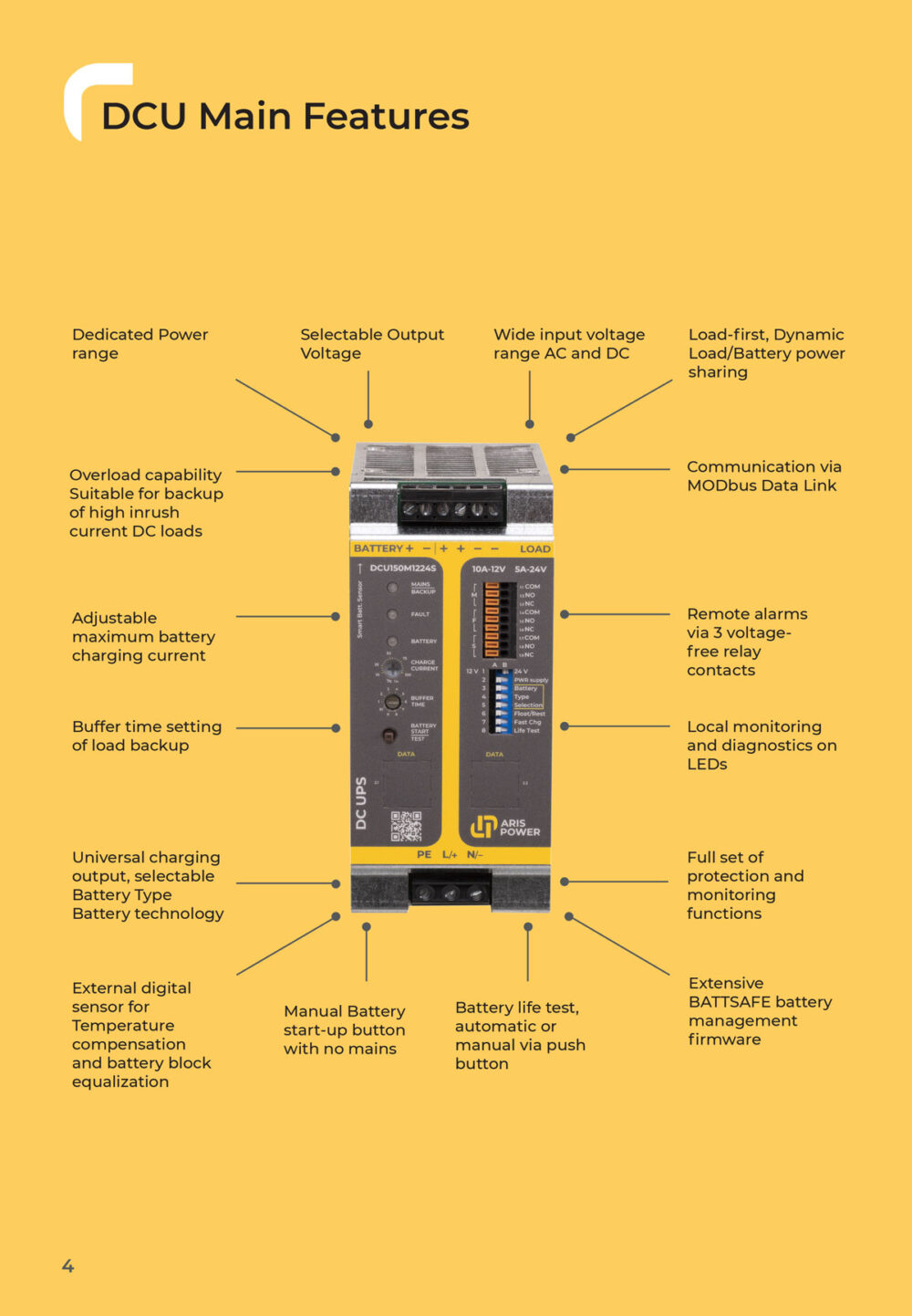
Dedicated Power Range
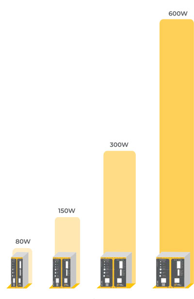
DCU units are available in the 80W to 600W power range. This range covers the requirements of most auxiliary circuits in applications.
Extension to 1 kW is under development
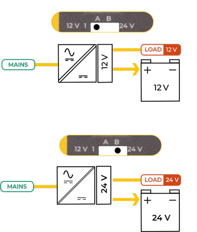
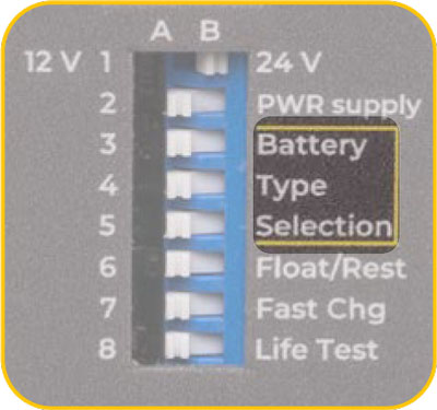
Selectable Output Voltage
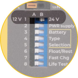
Wide input voltage range
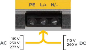
The DCU has a wide input voltage range making it suitable for connection to AC or The DCU mains. DCU is designed to accept AC mains with single-phase voltage rating 115–230-277 Vac, 47/440Hz or DC mains with voltage rating 110-240 Vdc
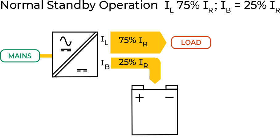
Load-first, Dynamic Load < > Battery power sharing
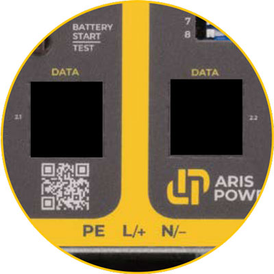
Data Link MODbus connectivity
on the front of the DCU, these are RJ45 connections. The interface is designed for MODBus-RTU communication protocol.
Remote alarms via dry relay contacts
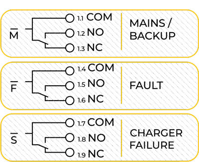
The DC-UPS is equipped with built-in alarms contacts, as follows:
- Mains/Backup
- Battery Fault
- Rectifier Failure
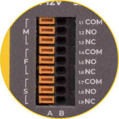
The three alarms are on dry change-over relay contacts and are brought to push-in terminals on the front of the device.
Diagnostics
During installation, operation and maintenance,device and system faults are also detected by auto-diagnostic features. Detected battery faults:
- Reverse Polarity connection
- Disconnected Battery
- Disconnected or missing Battery
- Detection of Wrong Battery Voltage
- Battery Cell in short circuit
- Wiring High impedance
- Life Test failed, replace sulfated battery
- Low Battery Voltage
- Battery almost discharged
- Battery fully discharged
Detected device/system faults:
- Overload or Short circuit on load output, standby
- Overload or Short circuit on load output, backup
- Rectifier failure
- Device internal failure
Local monitoring and diagnostics on LEDs
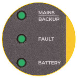
Three, three-colour LED indicators are available for visual monitoring of the DC-UPS on the device front.
- Mains/Backup LED
- Fault LED
- Battery LED
With blinking code, they provide a full set of status and diagnostic information, useful during installation and on-site inspection. For LED signaling and the corresponding states.
Monitoring
BATTSafe continuously monitors battery and device during operation, minimizes the risk of battery damage and allows a fully safe operation while keeping the battery in permanent connection with the DCUPS. Optimum battery life is the result.
Battery life test
The DCU is also a Battery Tester, automatic or manual via push button.
Automatic
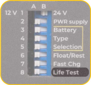
If the function has been enabled on the dipswitch, every two hours, while in Standby-Float charge, the DCU automatically performs battery life test.
Manual
Life test can also be performed on demand by manually pressing the Battery Start/Test push button for 10s. The DCU will run a full life test and negative or positive result will be shown by a blinking code on the LEDs.
Battery start-up
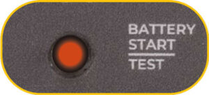
If the load must be powered up when mains is not available, the DC-UPS must be energized from the battery. This is manually enabled by the Battery Start push button.
This facility is particularly useful during commissioning when mains is not available to test load operation.
Temperature compensation Smart Battery Sensor SBS
The DCU is designed to perform temperature compensation of battery charging voltage. This feature optimizes battery efficiency and is a requirement often induced by norms such as EN54-4 fire protection norm or other equivalent international norms. This feature is enabled by connecting the Smart Battery Sensor accessory to the dedicated connector on top of the device.
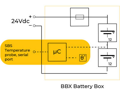
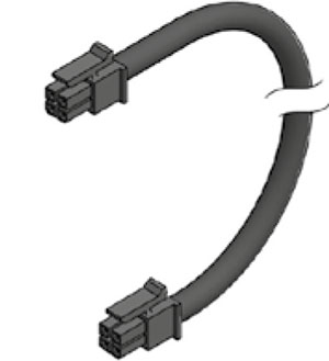
SBS is a built-in feature of Aris Power SBS-BBX battery boxes range. It also carries out battery block voltage equalization. Use the cable SBS002 to connect DCU and BBX. In case the DCU is charging a customer provided battery pack, the SBS001 sensor and cable shall be used.
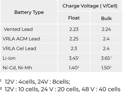
Universal Charger
BATTSafe firmware includes factory-set charging curves for the most common battery types: Vented Lead Acid, AGM and Gel Lead Acid, Ni-Cd, Li-Io.
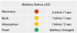
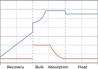
Automatic multi-stage IUoU Charger
BATTSafe performs automatic multi-stage charging following a stabilized voltages and stabilized current IUoU curve.
Recovery - flat batteries, when not irreversibly damaged, can be recovered. Fast Charge - If fast charging is required and compatible with the application, it can be enabled.
Buffer time setting
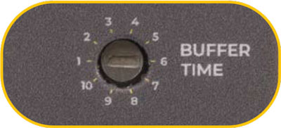
By default when in Backup mode, DCU will keep energizing the load until the battery is discharged, that is, LVD threshold is reached.
However, backup time requirement may be shorter than the time needed to reach LVD. To prevent unnecessary battery cycling in such cases, the DCU allows setting shorter backup times via the Buffer Time selector.
When the factory default setting is changed, please refer to the table below for the corresponding buffer time selected.
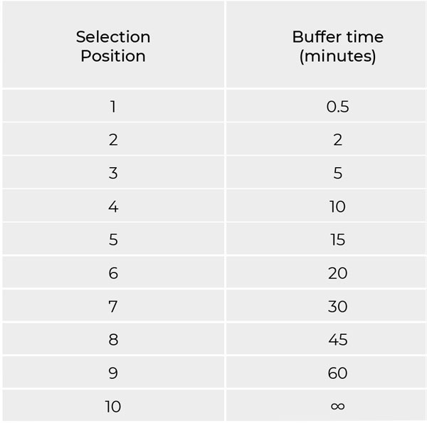
The maximum Buffer Time duration depends on the battery capacity rating and status of charge. Assuming backup occurs when the battery is fully charged, the times given in the table below can be used as reference.
Adjustable battery charging current
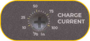
It is a key feature of the DCU. It allows to protect the battery from excessive charging currents and enables a safe and extended battery lifetime. The maximum Charging Current selector can be adjusted between 10- 100% of device rated current.
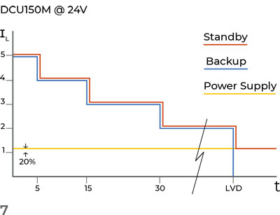
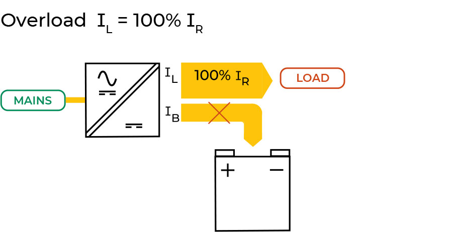
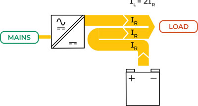
High Overload capability
The DCU architecture allows very high transient overloading capability and is therefore suitable for backup of DC loads with high inrush current.When load demands more than rated, Power Boost is enabled. The battery will start contributing to load power.
During Standby mode, part of the Power Boost will come from the mains via the DCU, part will come from the battery.
During Backup mode all Power Boost will come from the battery.
Unless the device is in Power Supply mode (i.e. without battery), when Boost is equal to +20% of IR. During the other modes, if the battery is fully functional, Power Boost will be limited in time according to overload current intensity.
To maximize battery Lifetime, the DCU disconnects the battery when it reaches the Low Voltage Disconnect threshold (LVD), preventing battery damages due to deep discharge.
Below this value, the device will autonomously switch off to prevent unnecessary discharge and consequent battery shorter life.